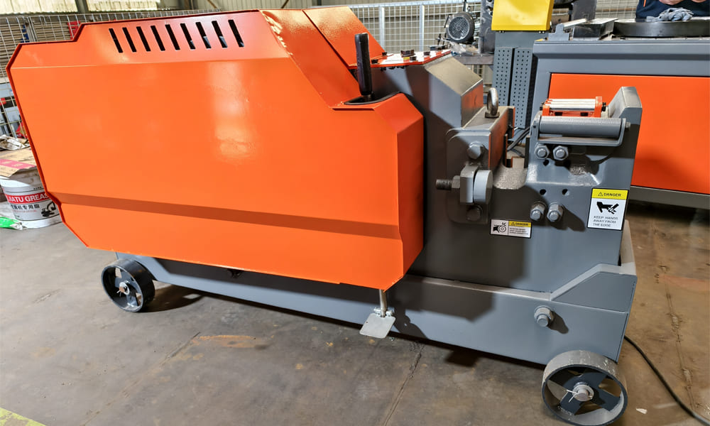
C52 Steel Bar Cutting Machine operates through a coordinated sequence of mechanical actions. Each component plays a specific role in guiding power from the motor to the blades, where the cutting force is finally delivered. The machine’s design can be explained by tracing the flow of motion—from energy input, to conversion, and ultimately to shearing.
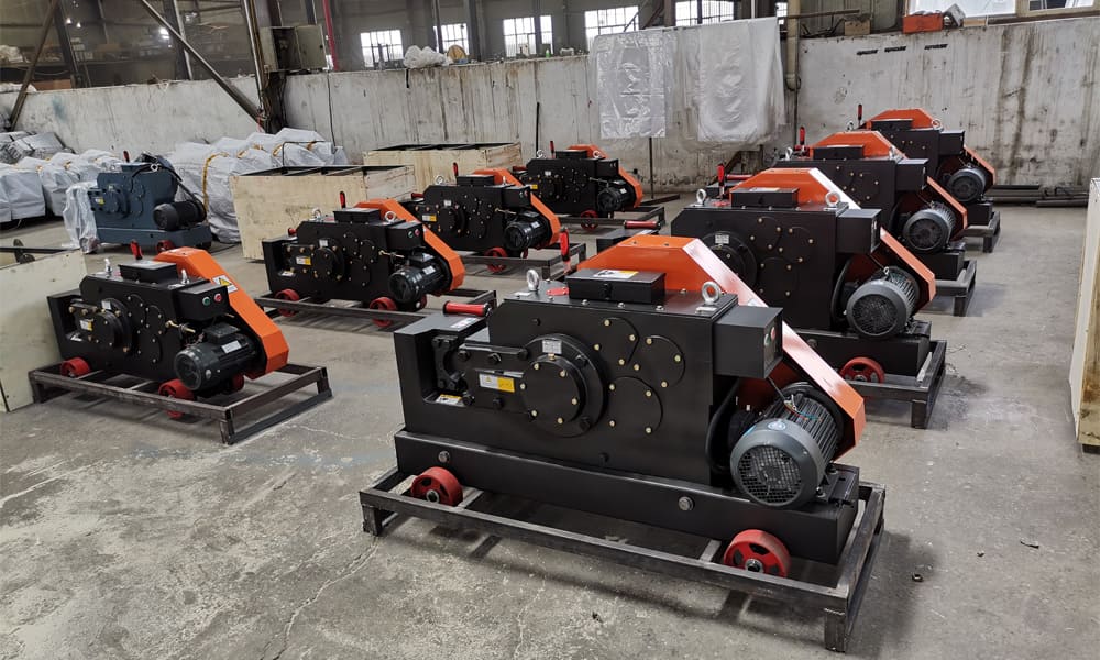
1. Power Delivery Stage
All machine functions originate from this foundational system.
Motor – The Initial Driver
The motor provides the rotational force that powers the entire cutter. Once engaged, it sets the complete transmission chain in motion.
Pulley and Belt Assembly – First Transfer Point
The motor’s rotation is passed to the next mechanism through a belt-and-pulley setup.
-
The belt cushions sudden loads, helping protect the motor.
-
The pulley moderates speed before torque moves into the reduction components.
2. Transmission & Motion Transformation Stage
This section adapts the motor’s rotation into the stroke required for shearing rebar.
Gear Train & Gear Shafts – Torque Amplification
A two-stage reduction system consisting of gears mounted on shafts lowers rotational speed while boosting torque.
These components rotate continuously and serve as the link to the next major part.
Eccentric Shaft – Converts Rotation into Stroke
The eccentric shaft changes circular rotation into a push-pull motion.
Its offset design generates the linear movement needed for the cutting action.
Connecting Rod – Linear Motion Transfer
Attached to the eccentric shaft at one end and the blade holder at the other, the connecting rod moves in a straight oscillating path.
It does not rotate—a common misconception—because its purpose is to relay the eccentric shaft’s stroke.
3. Cutting Assembly of the C52 Steel Bar Cutting Machine
This section produces the actual cutting force.
Blade Holder – Moving Framework
The blade holder slides back and forth under the motion supplied by the connecting rod.
It anchors the moving blade securely during each cutting cycle.
Moving Blade – Active Shear Element
Mounted on the blade holder, it advances toward the stationary blade to execute the shearing action.
Fixed Blade – Stationary Edge
Firmly fastened to the machine housing, the fixed blade remains immobile and acts as the opposing cutting surface.
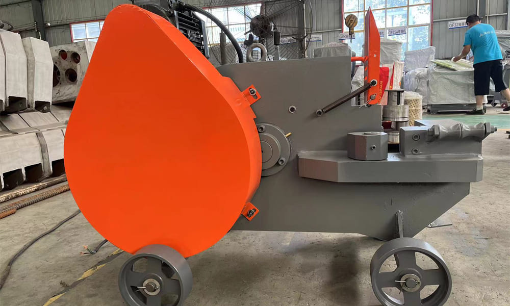
4. Structural Support & Stability System
These non-moving elements ensure strength, alignment, and vibration control.
Machine Body – Central Support
The housing keeps all mechanical parts correctly positioned and withstands operational loads.
Base Frame – Grounded Stability
The frame secures the machine to the floor, reducing vibration and maintaining a stable cutting position.
Complete Motion Flow Overview
Motor → Belt & Pulley → Gear System → Gear Shafts → Eccentric Shaft → Connecting Rod → Blade Holder → Moving Blade → Shearing Against Fixed Blade
This sequence clearly distinguishes:
-
Rotating components: motor, pulleys, gears, gear shafts, eccentric shaft
-
Reciprocating components: connecting rod, blade holder
-
Stationary components: fixed blade, machine body, base frame
By following this path, the function of every part in the C52 steel bar cutting machine becomes easier to understand, ensuring accurate operation and maintenance.