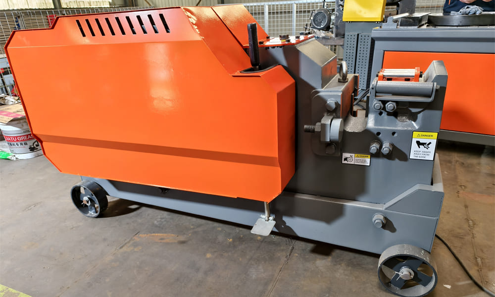
Italian-model C52 Rebar Cutting Machine is a benchmark equipment for processing medium- and small-diameter steel reinforcement, designed for cutting hot-rolled plain bars from φ10mm to φ52mm. It is widely used on construction sites and in rebar prefabrication workshops. Its engineering design effectively merges hydraulic and flywheel-based mechanical drive systems. Both versions operate on the foundational principle of efficient power transfer – precise blade movement – secure material clamping. While the blade trajectory and drive components differ according to the transmission type, the machine maintains distinctive Italian-model attributes such as a compact footprint, high structural rigidity, and robust operational versatility. This analysis examines three key aspects: core architecture, operational principles across drive types, and the interaction between blade motion and power transmission.
I. Core Architectural Overview of the Italian-Model C52 Rebar Cutting Machine
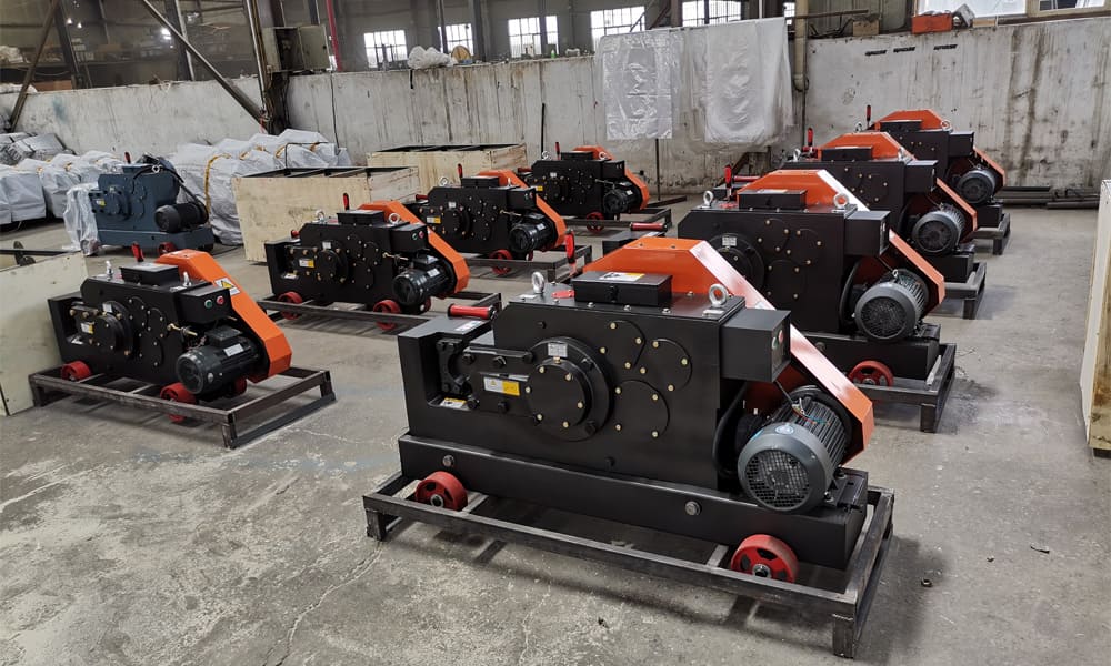
Mechanical flywheel variants of C52 Cutting Machine share fundamental structural components: a main frame, clamping mechanism, blade assembly, stationary blade holder, and scrap discharge chute. Design variations are confined to the power unit, transmission system, and moving blade actuator, tailored to suit each drive method. All parts adhere to the modular design philosophy and high-wear-resistance standards characteristic of Italian engineering. The core components and their functions are:
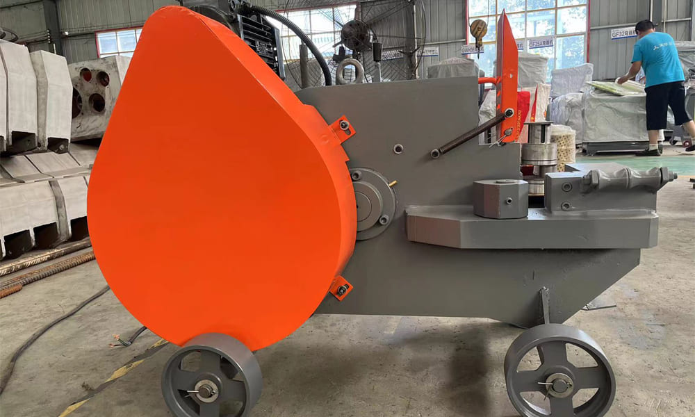
Main Frame: Constructed from a single-piece cast steel unit (or, in upgraded versions, welded thick steel plate with integral tempering), the frame is seamless. It houses internal cavities for the transmission and hydraulic systems. Vibration-dampening foot pads and mounting bolt holes at the base ensure overall stability during operation, preventing blade misalignment or rebar slippage—a key feature distinguishing Italian models from conventional designs.
Clamping Mechanism: This manually or semi-automatically operated linkage system employs a V-shaped clamp. Its design interlocks with the moving blade’s drive mechanism, automatically locking the clamp as the blade advances. The clamp is lined with high-wear manganese steel inserts to securely grip bars of various diameters, preventing rotation or axial movement and guaranteeing a clean, square cut.
Blade Assembly: Comprising one stationary and one moving blade, both are forged from high-alloy tool steel, heat-treated to Italian standards (quenched and tempered) achieving a hardness of HRC58-62. The stationary blade is mounted on the fixed holder at the frame’s front. The moving blade is rigidly attached to its drive mechanism (hydraulic piston rod or mechanical crank-slider). A wedge-shaped blade edge (30°–35° angle) minimizes punching force and reduces power consumption.
Stationary Blade Holder & Clearance Adjustment: This detachable cast steel component incorporates an adjustment bolt for fine-tuning the clearance between the stationary and moving blades (standard gap: 0.1–0.3mm). This allows compensation for blade wear, preventing material adhesion and deformation of the cut end. This user-adjustable clearance system is a hallmark Italian design, offering precision and operational simplicity.
Scrap Discharge Guide: Positioned beneath the cutting zone, this curved chute made of wear-resistant steel plate cleanly directs cut pieces away, preventing fragment scattering and minimizing impact wear against the frame.
II. Flywheel-Mechanical Drive C52 Rebar Cutting Machine: Operational Principles and Power-to-Blade Motion Mechanism
The flywheel-based mechanical drive represents the classic and original power configuration for the C52. It operates on a flywheel energy storage – gear reduction – crank-slider conversion principle, ideal for sites without external hydraulic power and with stable electrical supply. Its key benefits are rapid power response, high operational efficiency, and suitability for continuous batch cutting.
(I) Drive-Specific Core Components
Beyond the shared architecture, this version incorporates an electric motor, flywheel assembly, gear reducer, crank-slider mechanism, and clutch/brake system—all custom-designed to Italian specifications. Examples include a lightweight cast aluminum flywheel and a helical-gear reducer for quieter operation.
Flywheel Assembly: The core energy reservoir, consisting of a weighted flywheel disc and main shaft. As the motor spins the flywheel at high speed, it stores kinetic energy, which is released instantaneously during cutting to supplement motor torque, ensuring consistent power for cutting thicker bars.
Gear Reducer: A two-stage system (helical gear + spur gear) converting the motor’s high speed/low torque into low speed/high torque. Its output shaft connects to the crank-slider mechanism. The helical gear design ensures smoother engagement, reducing wear and extending service life.
Crank-Slider Mechanism: The central motion converter, transforming rotary motion into the linear reciprocation of the moving blade. It consists of a crank, connecting rod, slider, and high-precision rectangular guide rail. The minimal clearance between slider and rail guarantees blade movement straightness.
Clutch & Brake System: An electromagnetic clutch and band brake work in tandem to control machine cycling. Depressing the pedal engages the clutch, transmitting power; releasing it disengages the clutch and activates the brake, halting the flywheel and resetting the blade. This allows precise inch-mode operation and eliminates idle energy consumption.
(II) Operational Sequence
Powering the motor rotates the flywheel, storing kinetic energy. This energy is transferred to the gear reducer, where speed is lowered and torque amplified. The reducer’s output shaft rotates the crank through 360°, and via the connecting rod, drives the slider in a linear path along the guide rail. The slider, rigidly connected to the moving blade, propels it toward the stationary blade. Simultaneously, the blade’s forward motion triggers the clamp to lock the rebar. Shearing occurs upon full engagement of the blades. Releasing the pedal resets the clutch/brake, retracting the blade and releasing the clamp, completing one cycle. Continuous pedal engagement enables sequential batch cutting.
(III) Power Transmission Path & Blade Trajectory
Transmission Pathway: Motor → Flywheel Assembly → Gear Reducer (2-stage) → Clutch/Brake → Crankshaft → Connecting Rod → Slider → Moving Blade. This direct mechanical linkage ensures minimal power loss (over 85% efficiency). The flywheel’s stored energy provides stable instantaneous torque, enabling single-stroke cutting of bars up to φ52mm.
Blade Motion Trajectory: The moving blade follows a pure linear reciprocating path, perpendicular to the rebar axis. Path straightness is governed by the precision of the crank-slider guide rail. The blade stroke is fixed (C52 standard: 80–90mm). Cutting speed is uniform with a final acceleration phase as flywheel energy releases; blade impact speed reaches 1.2–1.5 m/s. This ensures a clean cut surface, minimizing pull-drag and excessive burr formation.